In the past I’ve discussed the idea of being able to recover context by test thinking. Here I want to reframe that idea a bit by recovering the context of what automation was like in the early 1980s. I think it’s important for testers to know their history. So let’s dive back to the 80s where, to quote Back to the Future, “we don’t need roads” — but we did need tests!
In order to give a bit of a period flavor, I’m actually going to use a relevant example that could be found in Byte Magazine; specifically the May, June and December 1980 issues that talked about the idea of “computerized testing.” To give some period flavor as well as to provide historical verisimilitude for my account, I’m going to use some images from those publications.
The Test Context
Let’s give ourselves a context that was very prevalent in the early 1980s. You work for a custom electronics manufacturer and your company has accepted a contract to produce a certain number of sequential controller boards.
Sequential controller boards are used for lots of things, most notably cars (such as for tail light control), washing machines (for the various cycles), automatic cameras, and so on. Sequential control refers to a type of control system in which the individual steps are processed in a predetermined order. This means that progression from one step in a given sequence to the next is entirely dependent on some defined condition(s) being met.
For all practical purposes, the “board” in sequential controller board refers to a small microcomputer that has various output combinations that trigger in response to designated inputs. You, as the resident tester, have the responsibility for testing the controller board. To keep things simple, let’s say the following is all true:
- The controller board has ten inputs and ten outputs.
- When a particular input signal is received, the controller activates one or more outputs.
- The controller then waits a preset time limit.
- The controller then changes the output.
Depending upon the input-signal combination, the sequence — the control flow — may have one to five steps. Also worth noting is that the timing intervals can also vary within each sequence. If that sounds like a recipe for race conditions that modern testers are all too familiar with, well, congratulations. You just learned that testing in the 1980s had many of the same logistics as today. In fact, what I just described there is essentially a system that has test and data conditions, really no different than any system you would test today.
But my goal here isn’t so much to compare “then” to “now”, but rather just to give you a taste of what “then” was like.

Automating Like It Was 1980
So let’s say we have a serial/parallel I/O interface for some peripheral called the COMM-80. This is the control board in question that we want to test. A visual you would have seen printed of such a device back in those Byte Magazine issues would have been (and you can click the image to see a bigger view):

That shows you a block diagram of what was called the COMM-80 110 interface. More specifically, that diagram is showing the interrelationship of the signals that pass through the board. The COMM-80 was an interface designed specifically for the TRS-80 although it could be attached to any 8-bit computer that had a bidirectional data bus. You’ll be forgiven if you’re hearing a distant echo of, “Well, we designed it on Chrome but, really, it should work in any browser.”
The COMM-80 contained a software programmable serial port and an 8-bit parallel I/O printer port. The COMM-80 also had variable-address selection and full RS-232C handshaking capability. In case that latter term isn’t familiar, RS-232 is a long-established standard that describes the physical interface and protocol for relatively low-speed serial data communication between computers and devices that can communicate with them.
So the COMM-80 was your control board; your system under test. The above block diagram is, in essence, your requirements. Further, in describing the component to you, I basically gave you the overall test conditions:
- Address Selection
- Printer I/O
- RS-232C Handshaking
- Serial I/O
Certainly you could test all this manually but, keep in mind, these were constructed boards and, as such, your company probably didn’t know how many they would produce. It could be one thousand. It could be one million. So testing all of that by human operation would soon get tedious. Thus you really want to use automation to support the testing of something like a COMM-80. On the other hand, also note that if the plan was only to produce, say, ten or even fifty boards, perhaps automation would not be worth it.
The Test Sequence
In this context, most automated test tooling consisted of a microcomputer and some front-end interfacing hardware. So let’s say the TRS-80 was to be used as the test computer. That means you would be writing your automation to code to execute on that machine. Now, technically you could use assembly language if you wanted the test to be lightning fast. But that comes at the cost of perhaps making the tests totally not understandable. Also since the TRS-80 was only one of the computing platforms to consider, assembly language would mean you would be writing your test setup multiple times.
So, instead, you might opt to use a higher-level language. You didn’t have all that many viable options available in 1980 for this. So, in this case, we use TRS-80 BASIC. BASIC was certainly more portable across computing architectures although it did diverge in its implementations. This means you would actually want your automation to be written written so that it can be executed on as many similar BASIC implementations as possible.
The front-end equipment would consist of a serial and parallel port. Uh, but hold on. Where actually do those come from? Well, these would actually be another COMM-80 that is set at an address (hexadecimal address 37F8) that was different from the test unit. So, yes, you would likely be using a COMM-80 in order to help you test a COMM-80. The idea was that when the test unit was exercised, the computer used in the test would read the results through the second (master) unit. The second unit was required only to provide the computer being used in the test (the TRS-80, in this case) with the proper serial/parallel I/O capability.
Here’s what that looked like.

That’s a TRS-80 system and the test equipment for the COMM-80. Specifically, the COMM-80 unit that’s under test here is the one on the left with its cover removed and all the cables attached to it.
As I described earlier, there are four major tests involved and special cables were required to attach the test unit to the master unit to support those tests. You can get a feel for that set up here:

These are the test cables required to run the tests on a COMM-80 serial/parallel I/O interface.
- The cable on the top connects the test-unit printer port to the master-unit printer port. The 8-bit parallel output is also wired to a sixteen-pin dual-in-line plug header to test the programming-plug input.
- The cable on the bottom connects the test unit RS-232C signals to the master unit’s RS-232C port.
I’ll note here that the board also contains a beeper that is triggered when the computer outputs data through the test-unit printer port. When all is attached, the setup appears as such:

This is a production COMM-80 under test with cables attached. You essentially have what today we could call a “test harness.” A second unit beneath, which is harder to see in the picture, provides the TRS-80 with the necessary I/O capability to successfully interface to both a serial and a parallel port. To remind, the sequence of tests are (slightly amended from my previous list):
- Address Selection/Decoding
- Parallel I/O (TTL-level)
- RS-232C Handshaking
- Serial I/O
The TTL in the second point refers to “transistor-transistor logic” and, for now, all you really need to understand is that this is logical circuit design that permits switching and maintaining logic states.
A flowchart for the sequence of test routines is shown here:

These flowcharts were effectively how you wrote up your test plans for this stuff back in the day. The above is a high-level test plan, of course. We’ll break that down as we go along examining the individual tests.
Test 1: Address Selection/Decoding
A little context: the “address selection” section of a peripheral device determines where within the computer’s addressing range the computer will find the peripheral. For the COMM-80, there are sixteen locations between hexadecimal locations 3708 and 37F8 to which it can be set. Keep in mind our test equipment here was a TRS-80 so, to be compatible with standard software for the computer, the setting should be 37E8.
Generally speaking, the failure in address decoders was usually the switch and not the actual logic. This meant that it was not enough to set the unit for address 37E8 and presume that, if that worked, the rest of the addresses would also work. It wasn’t so much that you needed to test all sixteen addresses but certainly each one of the four selectable address bits needed to be checked. Shades of understanding how coverage mattered which all testers deal with.
Also worth noticing here that, just as today, good testers had to know the sensitivities of the systems under test, including the most likely failure modes. Testers then, just as today, had to consider the ideas of partitioning tests based on equivalence classes and thus boundary conditions.
It also didn’t hurt to have an idea of how to test viable combinations, meaning using the fewest possible tests for the highest possible diagnostic value. In this case, the general test strategy here is to check six combinations:
- All address bits on.
- All address bits off.
- One address bit on at a time.
The only way to determine if the test passed was to successfully accomplish I/O communication at each address.
Something else to keep in mind about the 1980s context: as a tester, you had to create a circuit that would facilitate this test. As a tester, you couldn’t really be too divorced from the technology you were testing. Contrast that with today where the answer to how familiar testers are with the technology is a bit more muddy. This is why I asked if testers should be a type of developer and why I’ve asked testers to act like a developer.
Here is an example that shows a 110 test cable that connects the master and test units:
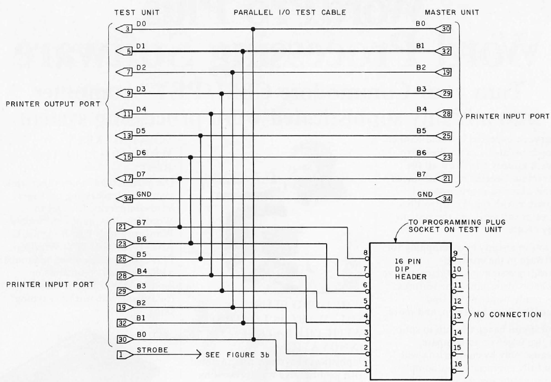
Incidentally, remember this image?
The cable on the top of that image is what’s being reflected in the above circuit. That’s what connects the test-unit printer (COMM-80 under test) port to the master-unit printer (COMM-80 supporting tests) port. The 8-bit parallel output is also wired to a sixteen-pin dual-in-line plug header to test the programming-plug input.
And here we have the beeper circuit that tests the address selection of the COMM-80:

If you’re curious about the historical details, the “beeper circuit” was just a really simple one-quarter-second buzzer circuit that was activated by the one millisecond printer output-strobe pulse. A strobe is a signal that is sent that validates data or other signals.
Only the address-decoder circuitry and the strobe-pulse generator on the COMM-80 board are involved here. The idea is that if a test unit is set for an address of 37E8, the beeper will sound every time the computer writes data to that address. In addition to providing a method for testing the address decoder, the beeper also serves as an audible indicator during other test sequences. So of an early “red-green” indicator for tests.
Here is the test sequence for the address-decoder test:

Now let’s consider our automation code. Here it is, in full glorious TRS-80 BASIC:
100 PRINT"************ ADDRESS CHECK **************"
105 REM THIS SUBROUTINE CHECKS EACH ADDRESS BIT OF THE ADDRESS
107 REM SELECTION SWITCH
130 PRINT"SET ALL ADDRESS SWITCHES TO THE OPEN POSITION"
140 GOSUB 510
150 POKE 14328,0
160 GOSUB 500
170 IF A$="@" THEN 180 ELSE 150
180 PRINT:PRINT"CLOSE SWI ONLY" :GOSUB 510
190 POKE 14200,0
200 GOSUB 500
210 IF A$="@" THEN 220 ELSE 190
220 PRINT:PRINT"CLOSE SW2 ONLY" :GOSUB 510
230 POKE 14264,0
240 GOSUB 500
250 IF A$="@" THEN 260 ELSE 230
260 PRINT:PRINT"CLOSE SW3 ONLY" :GOSUB 510
270 POKE 14296,0
280 GOSUB 500
300 IF A$="@" THEN 310 ELSE 270
310 PRINT:PRINT"CLOSE SW4 ONLY" :GOSUB 510
320 POKE 14312,0
330 GOSUB 500
340 IF A$="@" THEN 350 ELSE 320
350 PRINT:PRINT"ADDRESS TEST CONCLUDED...LEAVE ADDRESS SWITCHES IN THIS SETTING";
360 PRINT"FOR REMAINDER OF TESTS AND SHIPPING"
370 GOSUB 2500
380 RETURN
500 A$=INKEY$ :RETURN
510 PRINT"IF YOU HEAR A BEEP THEN PRESS AN @ KEY" :RETURN
2500 PRINT:PRINT:PRINT"PRESS ANY KEY TO CONTINUE TEST"
2510 IF INKEY$ <> "" THEN RETURN ELSE 2510
That’s automation from the 1980s, folks! Bask in the glory of yesteryear.
If you parse through that, what you’ll see is that, initially, all switches are set to the open position (hexadecimal address 37F8). The computer executing the test is then instructed to attempt to write to the printer at port 37F8. If the address decoder works, the beeper circuit should sound continuously. If that doesn’t happen, you probably found a bug. Once continuous beeping is achieved — and who doesn’t want continuous beeping, am I right? — you reset the address switches to hexadecimal address 3778 and press the @ key, as per the instructions in the test logic. This then instructs the computer used in the testing to try to write to printer port 3778. Once again, the beeper should sound.
But wait. How do you reset the address switches?

You just use the dual-inline plug switch, of course!
The sequence of actions I just described is then repeated five more times with the last address, hexadecimal 37E8, being left as the switch setting for all future tests. Important point there: the master unit (COMM-80 supporting the test) is permanently set at address 37F8 for all remaining tests. A bit of test leakage, as you can see, which means your tests had to be in sequence and did depend on previous tests.
In terms of time to execute, the above test took whatever time it took you to flip the switches and press a key. Which brings up the interesting point that there is still some human action needed in the context of this automation.
Test 2: Printer Port and Programming Plug
Another bit of context for you here: on the COMM-80 there was one full 8-bit parallel I/O port for the printer and one 8-bit option-select programming-plug input port. The latter had no physical connection to the serial hardware, but was used to set serial=communication options that were under software control. With the interface set at hexadecimal 37E8 (from our previous test), the programming plug is read as input port hexadecimal E9.
The concept behind this is to have the test unit send a data byte from its own output port to both input ports. The master unit reads the same eight bits to determine that they are set correctly. You could certainly just go from input to output (sixteen wires) between master and test units. I’ll leave it as an exercise for the reader to determine if anything better would be accomplished by taking that route.
Here’s the test plan for this:

That shows the sequence of operations of the parallel I/O test program. Here’s the TRS-80 BASIC listing that performs the test:
10 REM COMM-80 DIAGNOSTIC PROGRAM
20 REM
30 REM MASTER UNIT SET FOR ADDRESS F8-FB
40 REM
50 DATA 0,1,2,4,8,16,32,64,128,255
55 FOR X=l TO 10 :READ Z(X) :NEXT X
1000 PRINT:PRINT:PRINT" ******* PRINTER PORT AND PROGRAI1MING PLUG TEST *******"
1010 FOR X=0 TO 9
1020 POKE 14312,Z(X) :REM SET DATA ON TEST UNIT PRINTER OUTPUT
1030 S=PEEK(14312) :REM READ TEST UNIT PRINTER INPUT
1040 Sl=INP(233) :REM READ TEST UNIT PROGRAMMING PLUG
1050 S2=PEEK(14328) :REM READ MASTER UNIT PRINTER INPUT
1060 IF S+Sl+S2 <> 3*Z(X) THEN 1200
1070 NEXT X
1080 PRINT"PROGRAMMING PLUG AND PRINTER PORT CHECK OK"
1090 RETURN
1200 IF S2 <> Z(X) THEN PRINT"BAD PRINTER OUTPUT PORT --- FAILED ON ";Z(X);" DATA VALUE" :GOSUB 2500 :RETURN
1210 IF Sl <> Z(X) THEN PRINT"BAD PROGRAMMING PLUG INPUT --- FAILED ON "; Z (X) ;" DATA VALUE" :GOSUB 2500 :RETURN
1220 IF S <> Z (X) THEN PRINT"BAD PRINTER INPUT PORT --- FAILED ON ";Z(X);" DATA VALUE"
1230 GOSUB 2500 :RETURN
2500 PRINT:PRINT:PRINT"PRESS ANY KEY TO CONTINUE TEST"
2510 IF INKEY$ <> "" THEN RETURN ELSE 2510
That test takes about one second, incidentally.
Test 3: RS-232C Handshaking Test
A similar technique to what I just described would be used to check the RS-232C handshaking signals. The necessary interface cable is outlined here:

That’s a schematic diagram of the RS-232C interconnection cable between the master and test units. Remember: this was a circuit you had to build to run your test. By the way, one more call out to this image:
The cable on the bottom is what’s being described in the above schematic; it connects the test unit RS-232C signals to the master unit’s RS-232C port.
Here is the logic of the test:

That shows the sequence of operations of the RS-232C handshaking test. And, finally, here is the actual automated test itself:
60 DATA 0,0,0,2,128,48,1,64,192,3,192,240
65 FOR X=0 TO 3 :READ A(X) ,B(X) ,C(X) :NEXT X
2000 REM THIS SUBROUTINE CHECKS THE RS-232 HANDSHAKE LINES
2002 REM THE DTR AND RTS SIGNALS ARE TIED TO RI,CD,DSR, AND CTS
2005 PRINT:PRINT:PRINT"******* RS-232 HANDSHAKE SIGNAL TEST *******"
2010 POKE 14312,0 :REM SOUND BEEPER
2020 FOR X=0 TO 3
2040 OUT 234,A(X) :REM SET DTR AND RTS ON TEST UNIT
2050 D=INP(248) :D=D AND 192 :REM READ CTS AND DSR ON MASTER
2060 IF D<>B(X) THEN 2200
2070 E=INP(232) :E=E AND 240 :REM READ TEST UNIT LINES
2080 IF E<>C(X) THEN 2300
2090 NEXT X
2100 PRINT"        RS-232 HANDSHAKE SIGNALS CHECK OK"
2110 RETURN
2200 PRINT" MALFUNCTION ON DTR OR RTS OUTPUT SIGNALS" :RETURN
2300 PRINT"MALFUNCTION ON RI,CD,DSR,OR CTS INPUT SIGNALS":RETURN
There are two output signals on the RS-232C interface.
- DTR (Data Terminal Ready)
- RTS (Request to Send)
There are four handshaking signals on the RS-232C interface.
- RI (Ring Indicator)
- CD (Carrier Detect)
- DSR (Data Set Ready)
- CTS (Clear to Send)
Some of those handshakes were almost never used, but all had to be be checked and determined to be functioning. The test in this case is accomplished by tying the input to the output on the test unit (COMM-80 being tested) and monitoring the output lines again through the master unit (COMM-80 supporting the test). With two signal lines, there are four possible combinations. And, again, all had to be checked. Even with that requirement, this kind of test would still only take about one second.
Test 4: Serial I/O
The serial section of the COMM-80 incorporated a COM5016 data-rate generator and a COM2017 UART, where UART referred to “universal asynchronous receiver/ transmitter.” Both were programmable devices. Through them, it was possible to automatically set data rates, parity, word size, and stop-bit options. All of that could be done completely through software. This obviously made testing much easier since it allowed you to create your data conditions on the fly. It also, not incidentally, allowed you to eliminate the necessity of manually flipping switches as part of your “automated” test.
The sequence diagram for these tests is a little longer so you can click on each image if you want a larger view.


And here is the automated test:
50 DATA 0,1,2,4,8,16,32,64,128,255
55 FOR X=l TO 10 :READ Z(X) :NEXT X
75 DIM N(16)
80 DATA 50,75,110,134.5,150,300,600,1200,1800,2000,2400
85 DATA 3600,4800,7200,9600,19200
90 FOR X=0 TO 15 :READ N(X) :NEXT X
2500 PRINT:PRINT:PRINT"PRESS ANY KEY TO CONTINUE TEST"
2510 IF INKEY$ <> "" THEN RETURN ELSE 2510
3000 PRINT:PRINT:PRINT"******* SERIAL INPUT TEST *******"
3010 POKE 14312,0 :REM SOUND BEEPER AT START OF TEST
3020 GOSUB 3500
3030 FOR B=0 TO 15
3040 GOSUB 3600
3050 PRINT"CHECKING ";N(B);" BITS PER SECOND"
3060 FOR X=l TO 10
3070 OUT 251,Z(X) :REM LOAD MASTER UNIT WITH OUTPUT DATA
3075 IF B<5 THEN GOSUB 3950
3080 S=INP(234) :REM READ TEST UNIT STATUS REGISTER
3090 Sl=S AND 56 : REM MASK OR,PE, AND FE
3100 IF Sl>O THEN 3800
3110 IF SAND 128=0 THEN 3850
3120 D=INP(235) : IF D<>Z(X) THEN 3900
3130 NEXT X
3140 NEXT B
3145 RETURN
3150 PRINT:PRINT:PRINT"******** SERIAL OUTPUT TEST *******"
3155 POKE 14312,0 :REM SOUND BEEPER AT START OF TEST
3160 GOSUB 3500
3170 FOR B=0 TO 15
3180 GOSUB 3600
3190 PRINT"CHECKING ";N(B) ;" BITS PER SECOND"
3200 FOR X=1 TO 10
3210 OUT 235,Z(X) :REM LOAD TEST UNIT WITH OUTPUT DATA BYTE
3220 IF B<5 THEN GOSUB 3950
3230 S=INP(250) :REM READ MASTER UNIT STATUS REGISTER
3240 SI=S AND 56 :REM MASK OR,PE, AND FE
3250 IF SI >O THEN 3800
3260 IF SAND 128=0 THEN 3850
3270 D=INP(251) :IF DO Z (X) THEN 3900
3280 NEXT X
3290 NEXT B
3300 PRINT:PRINT:PRINT"TEST COMPLETE"
3310 RETURN
3500 OUT 232,0 :OUT248,0 :REM RESET MASTER AND TEST UNITS
3510 OUT 234,228 :OUT 250,228 :REM SET BOTH UNITS FOR 8 BITS,
3520 REM EVEN PARITY AND 1 STOP BIT
3530 RETURN
3600 OUT 233,B+B*16 : OUT 249,B+B*16 :REM SET EQUAL BAUD RATES
3610 RETURN
3800 PRINT"STATUS BIT ERROR":GOSUB 2500 :RETURN
3850 PRINT"NO DATA RECEIVED":GOSUB 2500 :RETURN
3900 PRINT"WRONG DATA RECEIVED":GOSUB 2500 :RETURN
3950 FOR A=0 TO 60 :NEXT A :RETURN
That’s actually the most involved test we’ve seen yet, at least if you go by the amount of logic. But it’s a little hard to parse. The essential idea here is that ten bytes of data (all on, all off, and each individual bit set) are sent from the master unit (COMM-80 supporting the test) to the test unit (COMM-80 under test) at each of the sixteen data rates. The communication path is then reversed and ten bytes are sent from the test unit to the master at each data rate to complete the test.
This might seem like a time heavy test.
Well, consider that the UART mentioned above was a hardware device. And it appeared to the computer used in the test (TRS-80) as a parallel port. So to send data, you addressed this port and loaded eight bits of data into it. At the conclusion of the output instruction, the UART automatically would convert this byte to serial format and transmit it at a rate that was dependent only on the transmit-clock input to the UART. “Transmit clock”? Uh oh. Nothing scary about the factor of time in tests, right?
So let’s consider the impact here. If this clock was, say, 800 Hz, then the information would go out at fifty bits-per-second. If, on the other hand, the clock was, say, 153,600 Hz, the information would go out at 9600 bits-per-second. From the automated test perspective, the only relevance of this was that at a faster bits-per-second, the next byte could be transmitted that much sooner. So it really wasn’t as bad as it sounded.
To read the incoming data, the test automation had to periodically read the UART-status register and checks to see if something called the the DAV (“data available”) flag was set. When that was the case, the test program read the data from the UART and reset the DAV line. Similar I/O-port manipulations like this would accomplish error checking and option setting.
Taking Our Leave of 1980
I’ll stop there. Obviously I had to give you a somewhat high-level view of the testing that was done in a very particular context. I certainly hope this was an interesting foray into how testing was done in many cases back in the glorious 1980s.
That said, all of this was leading up to a bit of a point. Specifically, one thing I do want to call out, and I’ll explore a bit in a follow on post to this one, is that, unlike today, testers then weren’t necessarily sitting there worrying about whether someone confused “human (operator) testing” with “computerized (automated) testing.” There wasn’t angst over denying the term “manual testing.” People didn’t feel the need to harp constantly on the distinction between, say, “testing” and “checking.”
Essentially people weren’t as confused about this as our industry sometimes seems to be these days. That is, very much, a lesson we should learn from the past.
With that said, I’ll see you back in the future (or, I guess, the present) for the next post.
