With the advent of 2025, I realized it was the forty year anniversary of one my earliest exposures to testing. This exposure involved helping an arcade operator test cabinet-based coin-op arcade games. I decided to try and recreate this context and allow others to do the same thing.
Why do this? Well, this does have some resonance with my post about testing like it was 1980. In this case, it would have been 1985, specifically. And the context was testing Defender, specifically with an arcade chain called Aladdin’s Castle.
(Fun?) Fact: I was originally going to call this post “Testing Arcade Games in the 1980s,” which is certainly what it’s about. But I couldn’t resist the double entendre of me being a defender of testing but also, more literally, talking about testing Defender!
This post is meant to be nothing more than a hopefully interesting trip down one aspect of testing history. I actually do have a Defender arcade cabinet, so I’ll show you some relevant bits as part of this just to set the stage for you.

Defender is a horizontally-scrolling “shoot ’em up” arcade game created by Williams Electronics. The company chose a guy named Eugene Jarvis, who had a successful record with Williams pinball games, to head development. A few other folks — Larry DeMar, Sam Dicker, and Paul Dussault — assisted Jarvis. The game was shown at AMOA in Chicago on 31 October 1980 and released a week or two later on 15 November 1980.
AMOA is an arcade industry trade show. Originally known simply as MOA — The Music Operators of America — it became the Amusement & Music Operators Association.
Defender featured amplified monaural sound and pixel graphics on a CRT monitor. A Motorola 6809 central processing unit (at 1 Mhz) handled the graphics and gameplay, while a Motorola 6800 microprocessor (at 894.75 Khz) handled the audio. I won’t cover the history of the game but you can read a good BitStory article about Defender.
Dealing with Cabinets
If you were dealing with a cabinet back in the day and you wanted to use an assembly unit for a full round of testing, you had to start taking apart the cabinet.
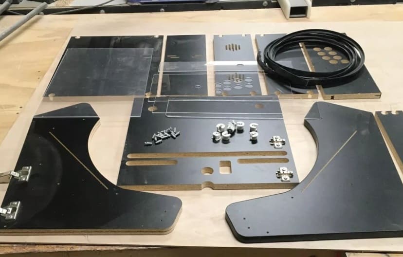
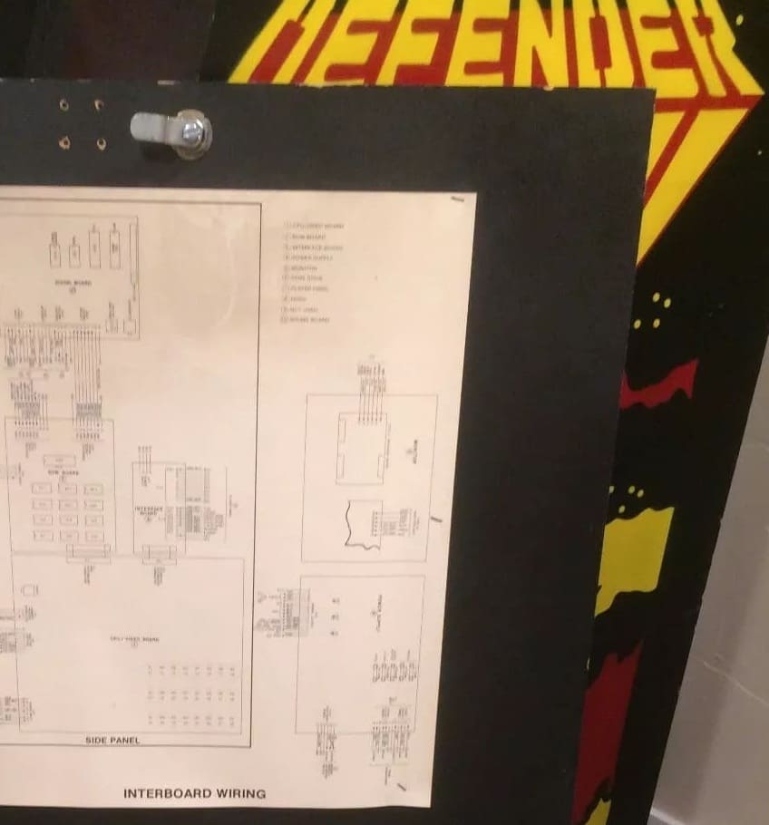
You had to remove the backdoor. The innerboard would likely have a schematic. If not, you were in a bit of trouble unless you had one of the manuals.
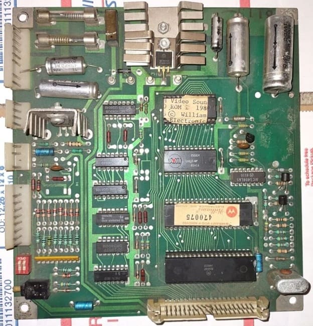
You had to then hook up the PCB (Printed Circuit Board) to some sort of power supply. Here’s how it looks if you do that today.

Those PCBs were, in fact, quite important. These games were made up of PCBs. Here are two of mine:
 |
 |
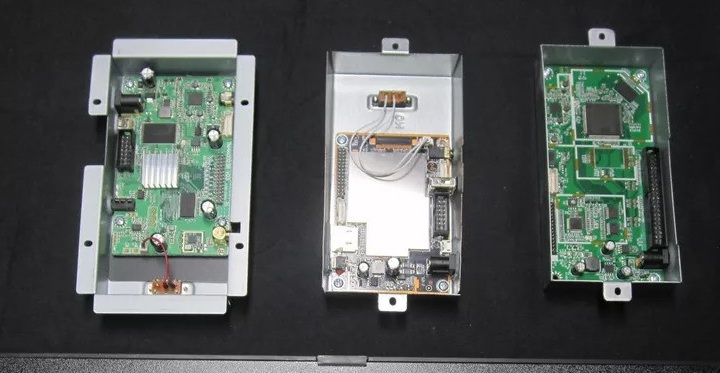
Here are three of the PCBs that you had to separate out and get ready for the testing.
Testing with Switches
So what exactly did you do once you got all the boards separated? Well, you had what were called test switches. This is basically what they looked like.

That right there is an arcade cabinet test-service switch assembly with, obviously, two switches. Here’s what they look like when they’re a little worse for wear, after surviving the ravages of forty years.
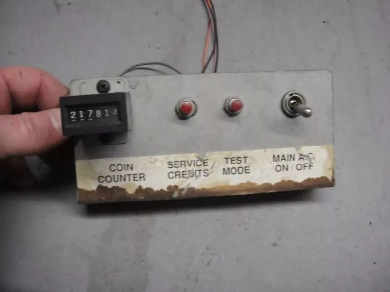
Rather than show you this stuff, which would take me a bit far afield from my recreation, I would direct to you some videos that show more detail. One of those videos is specifically about a Defender PCB service switch.
The general idea here is that the test switch brings the game/PCB into test mode for diagnostic purposes.
In arcade machines, the PCB was the main component that held and connected all the electronic circuits that made the game run. The term “PCB switches” refers to the switches or jumpers that were physically placed on the arcade game’s PCB to modify certain settings or control how the game operated. These were particularly common in older arcade machines before modern software-based configurations became more widespread.
There were different types of switches. There were DIP switches, where “DIP” stood for Dual In-Line Package. These were small, manually operated switches on the PCB that could be used to configure various game settings, like difficulty level, number of lives, bonus points, and game modes. This was stuff that a local arcade operator could choose to tailor.
An arcade operator might switch the difficulty level, for example, to a lower setting to get more people to initially play the game. Once you had a hooked audience, the operator would increase the difficulty level. There was an art to the timing of this!
The test/service switches were a variation on the DIP switches. These were special switches on the PCB used for maintenance or diagnostic purposes. Technicians could use these switches to access “test modes” or initiate coin mechanism tests, among other diagnostic features. These switches were often used to check the functioning of the game’s hardware or trigger certain game sequences.
Crucially, these switch mechanisms were a way to modify the game without requiring changes to the game code itself. While cerainly not “automated testing” in the modern sense (i.e., the game running without any human interaction), these service switches did make it easier for operators or technicians to validate critical gameplay and hardware functionality with minimal manual intervention. This setup helped ensure that the arcade games were running smoothly between player interactions, reducing downtime and making maintenance more efficient.
Notice the important point here: while the test/service switches on arcade PCBs were often used as a way to run diagnostic tests or trigger specific sequences that helped game operators or technicians verify the functionality of the hardware, they didn’t simulate actual gameplay. And therein lies the trick! This was a form of testing but a very limited form of it. As I quickly learned back in 1985.
In order to test the game itself, you had to hook those PCBs up to a computing system that could assemble the source code and generate a playable experience but one that was instrumented. Here’s a good example of what this looks like:

That happens to be running another game, SUPER STARS, but you can see how the PCB is directly connected up to a system where you could play the game as if it was in the arcade cabinet. The project I worked on for my anniversary nostalgia was to essentially recreate that on modern hardware.
Defender Retro!
My Defender Retro repository provides the basis for how to recreate what we did back in 1985, albeit with some virtual aspects to it and some updated tooling.
You can use that repository to assemble the source code from the actual Defender game back as it was in 1981 and get it into a playable form via a generated ROM, along with supporting files, that can be executed on an emulator. Details are in the repo so I won’t bore you with that here.
I also attempted to cross-generate a working example in Go called Defender RedLabel. That attempt is still not fully successful.
My repo does provide a reference ROM, it provides schematics, and it provides the bank code assembly.
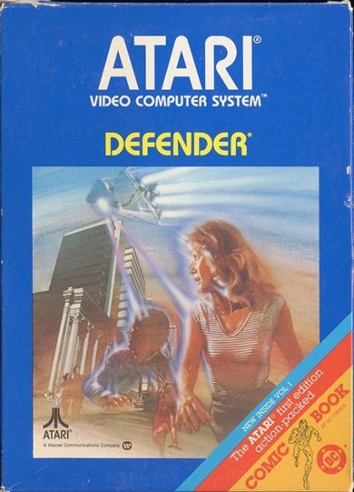
For extra fun, the repo even provides the disassembled version of the Atari 2600 version of Defender.
Testing All This!
Now, wait a minute. Would there have been value to a tester in having bank code assembly, fixed ROM code assembly and circuit diagrams? The answer is: yes! These would be — and were — immensely helpful in testing arcade games, both during development and for post-release maintenance or troubleshooting.
Bank Code
Bank code refers to the assembly code for the game that’s executed from specific regions or “banks” of memory. In arcade games like Defender, the game code was often split across multiple memory chips or regions of ROM to fit the hardware’s limited memory.
As a tester, you could use the bank code to debug specific game functions by inspecting the assembly code to trace logic errors, performance issues, or unexpected behaviors. For example, if enemies in Defender weren’t spawning correctly or the scoring wasn’t updating, testers could check the assembly for the routines responsible for these tasks. If something like a sprite wasn’t appearing on screen, the tester could check the corresponding assembly code for how sprites were handled and trace the issue.
If a bug was found during testing, you might even have been able to patch it. Knowing how to modify the bank code assembly was invaluable for creating a fix that could be loaded onto a new ROM or patched on the fly via service mode.
Fixed ROM
The fixed ROM refers to the portion of the game code that’s stored in read-only memory, which usually contains essential, unmodifiable parts of the game like the main program logic, graphics, sounds, and sometimes even the system’s firmware. The fixed ROM often contained critical, unchanging routines that control system startup, hardware initialization, and basic game flow.
As a tester, you could verify that the game properly initialized the hardware and ran without corrupting these fixed ROM areas. If issues arose with random errors or crashes, it was often due to bugs or memory corruption elsewhere in the system, but testing the fixed ROM code could rule out corrupt or faulty ROM chips.
As a tester, you could also cross-reference the game’s specific routines (in the bank code) with the fixed ROM code to see if there were any misalignments or compatibility issues. For example, if sprites were rendering incorrectly, it might indicate an issue with the code that pulls sprite data from the fixed ROM.
Circuit Diagrams
Circuit diagrams show how the hardware components are physically connected to one another, from the CPU, memory, and graphics chips to input/output devices like joysticks, buttons, and the monitor.
As a tester, you could use the circuit diagrams to trace hardware failures or diagnose issues that weren’t software-related. For example, if the game wasn’t displaying anything on the screen, the circuit diagrams would show the connection between the video output and the CPU, helping to track down issues in the hardware. If the game’s response time or behavior was inconsistent, you could use circuit diagrams to check the flow of data between components, ensuring that the signals were being correctly transferred between memory, the processor, and output devices.
ROM Versions or Labels
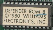
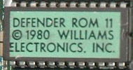
What matters in these arcade games are the ROMs. These are the binary game files that are essentially read-only memory. Defender ROM sets were distinguished by early and later editions. The early edition supported only upright cabinets. In 1981, Williams released what was called a cocktail cabinet version and that necessitated extra code to flip the video display and to support a second set of game controls.
So you had early edition ROM sets, which were called White Label, Green Label, and Blue Label.
 |
 |
 |
You had later edition ROM sets, all of which were effectively called Red Label, although there were “types” of Red Label.
 |
Red Label Type 1 |
 |
Red Label Type 2 |
 |
Red Label Type 3 |
As a technician, it mattered which ROM set you were dealing with. Each release was a circuit board with the assembled code split across a number of different ROM chips. To create a testable version of the game, you had to be able to to generate code that would run on a computer but that would accurately simulate the code that was on a specific ROM chip.
This was crucial! If you didn’t do this, you weren’t actually testing the game as it would be executed in the arcade cabinet. Although getting this part wrong would likely mean the game wouldn’t run anyway.
The source code for these games was written in assembly language. In the case of Defender, this was for the Motorola MC6809. All of what I just described is what I had to reproduce as part of my GitHub repository.
Trying It Out!
How are you supposed to compile all this? Well, we have the original source code and Eugene Jarvis left an interesting note regarding how to assemble the source in the info.src file. Jarvis’ statement is brimming with confidence: “TO ASSEMBLE THE DEFENDER MESS”.
This is a message from 21 January 1981, folks!
What his note tells us is that Jarvis was using an assembler called RASM. This was a popular assembler for the Z*0 microprocessor. We don’t have access to that in any useful sort of way but what we can do is use asm6809. This is what my project includes as a submodule. ASM6809 is a portable cross assembler targeting the Motorola 6809 and Hitachi 6309 written by Ciaran Anscomb. The assmebler itself is written in C and is licensed under the GPL.
I should note that due to differences in the assembly process, using ASM6809 did require modifications to the source files to produce the binaries.
This project will generate the ROM files that you see in the build directory. Take a look at that build directory. Do you notice anything interesting?
You’ll probably notice that there’s no defend.5 file. Why is that? As a tester back in 1985, I can assure you that when you first built the ROM, if you didn’t have certain knowlege, this would confuse you and you would be certain that you did something wrong. However, consider this view of an actual board for the Red Label PCB:

That’s a Williams 5771-09615-X0 D8572 ROM Board. Notice there’s a chip missing there? This is what you would have pulled out of the actual arcade cabinet. Yikes! So you pull out your trusty Williams specification. Take a look at the circuit diagram:

That missing chip looks to be Chip 5. Ah, so we’re missing a part, right? Well, you double check to see the part designation for the game.

Notice how IC5 is “NOT USED.” So that make sense. This is also confirmed in a separate set of schematics for the circuit board. This was actually how you knew that your building of the software was actually accurate!
What all of this shows you is that each file defend.[x] corresponds to a matching chip on the board and because there is a missing chip in slot 5 we have no “defend.5” in the ROM dump listing.
So what this repo lets you do is assemble the Defender source for the Red Label implementation, which means you have to create a bunch of object files and then split those object files across eleven files to match the eleven chips in the Red Label PCB.
The project Makefile contains everything you need. The “Build Main Code + Attract” step takes care of the main game code with the attract mode module assembled in.
The attract mode is used to demonstrate the gameplay of the game, and “attract” players into spending their money on the game.
The file phr6.src is a file containing definitions, while defa7.src and defb6.src contain the main game code itself. The amode1.src contains the attract mode code. You also have to build a version of this game code without the attract mode module, which is what “Build Main Code – Attract” section does.
However, keep in mind those 1981 ordering notes! In between those two above steps, we have to build samexpa7. This is a bunch of explosion routines added by Sam Dicker. Note the mention in that file of “ASSEMBLE WITH PHRED.” PHRED was a particular assembler that was often used for the 6502 microprocessor, and you would see it used with systems like the Apple II and the Commodore VIC-20 and Commodore 64. Handling this file is what the Makefile section “Build Sam Explosions and Appearances” handles.
That still leaves us with the files mess0.src, blk71.src, romf8.src, romc0.src, and romc8.src. It’s not entirely clear what to do in terms of assembling those. However, once again, we can turn those 1981 notes. It seems that the way Jarvis listed the files was meant to guide someone towards how to assemble them. It would seem that we can assemble the last four together in the order that they appear in his list. That’s what the “Build game ROMs” Makefile section does but, before that, we can build the one remaining file, which is mainly about terrain data. The Makefile section “Build game terrain” handles that.
The last thing we have to build in is the sound. But we need some extra tooling to help with that. We’ll need VASM to compile the sound module. That’s what the Makefile “Build game sound” section handles.
VASM is a portable and retargetable assembler to create linkable objects in various formats or absolute code. Multiple CPU, syntax and output-modules can be selected. It’s under a free license.
With all that, you now have some binaries built. We still have to replicate the arrangement of the contents of the ROM chips to the assembled code. This requires extracting the relevant segments from each of the binaries that were built. From the gathered sources and schematics, it’s clear (after much parsing!) how this mapping is done.
| ROM Chip | Part Number | File Name | Build Binary | Start Position | End Position |
|---|---|---|---|---|---|
| IC1 | A5343-09636 | defend.1 | bin/defa7-defb6-amode1.o | 0xb000 | 0xb800 |
| IC2 | A5343-09637 | defend.2 | bin/defa7-defb6-amode1.o | 0xc000 | 0xd000 |
| IC3 | A5343-09638 | defend.3 | bin/defa7-defb6-amode1.o | 0xd000 | 0xdc60 |
| IC3 | A5343-09638 | defend.3 | bin/samexpa7.o | 0x0000 | 0x02f8 |
| IC3 | A5343-09638 | defend.3 | bin/defa7-defb6-amode1.o | 0xdf59 | 0x0230 |
| IC4 | A5343-09639 | defend.4 | bin/defa7-defb6-amode1.o | 0xb800 | 0x0800 |
| IC5 | Not Used | ||||
| IC6 | A5343-09640 | defend.6 | bin/blk71.o | 0x0000 | 0x0772 |
| IC6 | A5343-09640 | defend.6 | bin/roms.o | 0xa778 | 0x0088 |
| IC7 | A5343-09641 | defend.7 | bin/roms.o | 0xa000 | 0x0800 |
| IC8 | A5343-09642 | defend.8 | bin/roms.o | 0x0000 | 0x0800 |
| IC9 | A5343-09642 | defend.9 | bin/defa7-defb6-amode1.o | 0x0000 | 0x0800 |
| IC10 | A5343-09643 | defend.10 | bin/roms.o | 0xa800 | 0x0800 |
| IC11 | A5343-09644 | defend.11 | bin/roms.o | 0x0800 | 0x0800 |
| IC11 | A5343-09644 | defend.11 | Unknown | 0x0800 | |
| IC12 | A5343-09645 | defend.12 | bin/defa7-defb6-amode1.o | 0x0800 | 0x0800 |
| IC12 | A5343-09645 | defend.12 | bin/defa7-defb6-amode1.o | 0xaee9 | 0x0117 |
What happens, when all is said and done, is that the source code is assembled into the eleven ROM files that would have been loaded onto the arcade cabinet’s ROM board.
If you think this is complicated now with a repo that does most of the work for you, please imagine what this was like in 1985!
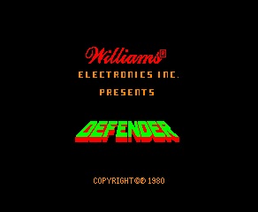
If you truly want to play around with this, there are instructions in the README for the project. I also provide the fully assembled outputs that would be needed to play this in an emulator like MAME, if someone doesn’t want to go through the hassle. If you fire up the ROM in MAME, you’ll get some Defender goodness!
 |
 |
You’ll note the repo requires the use of C, Python, and Assembly, along with a helping of Make. Python wasn’t around in 1985. We didn’t get that until 1991. Make has been around since 1976 but GNU Make wasn’t around until 1988. So even with this nostalgia trip, you’re still not really getting the true feel of what it was like. I guess you just had to be there!
I’ll close with this: if you could do all this stuff back in the day, you were considered quite cool! Indeed, folks, the 1980s was an era when “testers” (even if we went by the name technician) were — in the lingo of the era — hip, rad, gnarly and tubular (to the max!)